Mechanical engineering tools are instruments, devices, and programs that help engineers turn ideas into real mechanical parts and systems.
They support many disciplines by helping with design work, testing steps, clear checks of dimensions, and safe use of equipment.
These tools guide the knowledge that teams need to work in the industry and give a clear path from concept to final build.
In this article, we’ll list 14 essential tools and explain how each one fits into daily engineering work.

Types of Mechanical Engineering Tools
Mechanical engineers use a variety of tools for making physical products. These are categorized into two groups:
- Handheld tools: Manual tools and small devices that engineers use for measuring, shaping, or simple testing. They are used for tasks requiring precision, control, and direct physical manipulation, such as measuring, assembling, shaping, or testing mechanical components.
- Digital tools: Software solutions that help engineers design, simulate, analyze, and manage mechanical systems. They support 2D and 3D models, digital prototypes, and early performance checks to study how an example design will behave before building it.
9 Handheld Manual Tools for Mechanical Engineers
Mechanical engineers work with many small tools that help them test parts, check dimensions, and fix equipment. Let’s look at the common ones engineers regularly use:
1. Screwdrivers
Screwdrivers help turn screws during assembly or repair work. Mechanical engineers use them when they need to fix or adjust machinery or tighten bolts in a system.
They also help during testing when a cover or panel needs to come off so the engineer can look inside a part.
2. Calipers
Calipers give precise measurements of metal or plastic parts. Engineers use them in science and design work to confirm that dimensions match what the drawing calls for.
This helps them check if a part from new machines meets the needed size before it goes into a build.
3. Digital Force Gauges
A digital force gauge measures pulling and pushing forces. It shows clear readings that help engineers check how strong a part is.
Some teams also use a push-pull force gauge when they need to test a part in both directions. These tools help confirm that components can handle real loads during building or field use.
4. Ohmmeters
Ohmmeters check resistance in electromechanical parts. Engineers use them to confirm that the electrical path inside a device is correct.
This is helpful when a system mixes gears, wiring, and other functions. If something stops working, the ohmmeter helps find the problem fast.
5. Flow Meters
Flow meters measure how fast a fluid moves through a line. Mechanical engineers use them when they work with HVAC units, cooling loops, or any setup that needs clean fluid flow.
These readings guide them when they want to create a smoother process or fix a drop in performance.
6. Graphing Calculators
Graphing calculators help mechanical engineers solve math problems on the spot. They can handle many types of equations and show plots that make the problem easier to understand.
Engineers often use them during testing or early design work when they want quick answers.
7. Cold Forming Presses
Cold forming presses shape metal without heat. Engineers use them to make custom bolts or small parts for prototypes.
This helps them learn how a shape will hold up before they send the final design to milling machines for more advanced work.
8. Pliers, Tape Measures, Wrenches, and Allen Keys
These tools help grip, measure, and turn parts during daily work. Engineers use them to adjust machinery, remove covers, or fix alignment issues.
Tape measures help check fit inside tight spaces, while wrenches and Allen keys handle bolts and hex screws. Some teams also keep vibration isolators nearby when they measure vibrations or adjust parts that may shake.
9. Drafting Compass
A drafting compass helps engineers draw clean arcs or circles on paper during early ideas or quick planning.
It supports concept work in a course or lab and gives teams a simple way to mark layouts before they move to a full design.
5 Mechanical Engineering Software Tools
Much like manual tools, engineers also use a variety of software to support CAD design, analysis, and testing work. Let’s look at five common software programs they use for daily work:
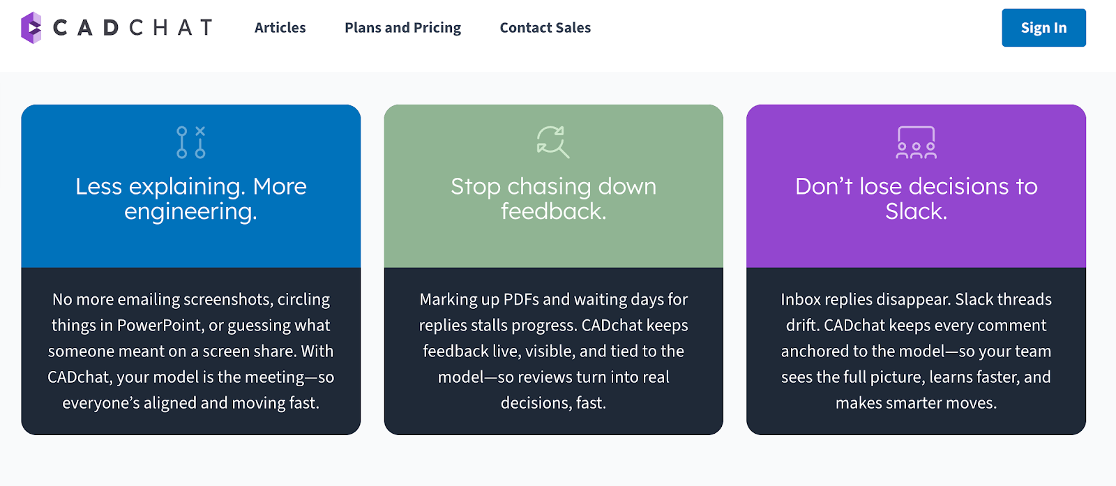
1. CADchat for CAD Collaboration

CADchat is a meeting tool made for mechanical engineers who want real-time design feedback without slow screen shares or lost notes. Engineers and designers can open the 3D model, talk through it with the team, and make progress in real time.
The model is right in front of everyone, so there is no confusion about parts, materials, or components. Feedback stays with the geometry, which helps teams save time and move from talk to action with less back-and-forth.
It works with major CAD formats, brings engineers and suppliers into the same space, and keeps every design choice tied to the right view.
Key Features
- Live CAD model reviews: Teams view and inspect native 3D CAD files together in real time. This removes the need for screen sharing and keeps all views clear and accurate.
- Real-time DFM and manufacturability input: Machinists and suppliers can join a session and point out issues on the spot.
- Simple for non-technical partners: Executives, supply chain teams, and marketing can join a session and give clear input without using CAD tools.
- Built-in version clarity: CADchat works with major CAD formats and opens the most current model.
- Feedback tied to the model: Comments and snapshots stay attached to the geometry. Nothing gets lost in email or chat threads, and the team can return to the same view at any time.
- Fast start for any team: Teams can join a meeting from a link with no installs. This makes it easy to invite vendors, clients, and suppliers who need to see the model.
- Wide CAD support: Teams open SolidWorks, STEP, Inventor, and more with no conversions. Engineers can inspect parts, materials, and components right inside the tool.
- Secure for sensitive work: SOC 2 level security keeps design files and intellectual property protected during reviews.
Simplify how your team reviews 3D models and makes design changes. Get started with CADchat today!
2. Autodesk for CAD Modeling

Source: autodesk.com
Autodesk AutoCAD is a widely used CAD software solution that supports detailed 2D drafting and full 3D modeling. It gives engineers access to tools that help them shape ideas, analyze design data, and work with complex parts through clear and flexible workflows.
The CAD software supports precise geometry, automation features, and a mix of desktop, web, and mobile access. Teams can work in the same drawing, share updates, and keep design files connected across projects.
AutoCAD combines strong technology, reliable engine performance, and broad capabilities that help engineers model parts, check layouts, and manage changes without slowing down their process.
Key Features
- Advanced 2D and 3D tools: Engineers create and edit detailed geometry, surfaces, solids, and mesh models with precision.
- Automation support with Autodesk AI: The software helps automate drafting tasks, compare drawings, and place objects with smart tools that use design data.
- Flexible collaboration options: Teams can open, review, and share DWG files across desktop, browser, and mobile so projects stay connected.
- Customizable workspace: Users can shape the interface with AutoLISP, APIs, and apps to match their workflow and expand the tool’s capabilities.
- Integrated document management: Design files connect to Autodesk Docs so teams can manage versions, approve changes, and review updates across projects.
3. ANSYS for FEA

Source: ansys.com
Ansys is a finite element analysis (FEA) tool that helps engineers study structural behavior, thermal performance, vibration, and complex nonlinear effects in one place.
It supports detailed models with contact, materials, and large assemblies, and it gives teams the freedom to test many design paths without building physical parts.
Engineers can study fluid flow effects, air flow forces, thermal loads, and stress behavior to help guide decisions early in the design process.
Key Features
- Full structural and thermal analysis: Engineers study stress, deformation, heat transfer, and material behavior across simple or complex models.
- Support for fluid flow and air flow loads: The tool connects to multiphysics setups so teams can apply pressure fields or flow effects directly to their structural models.
- Advanced material and contact modeling: Users work with nonlinear materials, frictional contact, and large deformation to represent real engineering conditions.
- Fast solvers for large models: Parallel solvers handle big assemblies and transient studies with strong performance and stable results.
- Automation and parametric studies: Engineers adjust variables, set up design sweeps, and automate repeated runs to explore many design options with less manual work.
4. Solid Edge for 3D Printing

Source: solidedge.siemens.com
Solid Edge gives engineers a clear path from early ideas to ready-to-print parts. It supports the full process, from shape exploration to print setup, so engineers can move fast and test designs without extra steps.
The software works well for prototypes and final parts and helps build geometry that fits the needs of additive manufacturing.
Engineers can prepare models, mix mesh and solid bodies, send files to a printer, or connect to online services for instant quotes and material options. This makes it a practical tool for teams that want simple control over their 3D printing work.
Key Features
- Generative design tools: Engineers explore shapes with topology optimization that helps create light, complex forms suited for additive manufacturing.
- Mixed solid and mesh modeling: The software handles solid bodies and mesh models together.
- Direct print output: Users can export parts to STL or 3MF or send them to the Microsoft 3D Builder app for fast print setup.
- Support for color printing: Solid Edge prepares models for printers that use color, which helps with prototypes and presentation parts.
- Access to online print services: Designs can be sent to cloud services for instant quotes, material choices, and delivery to a chosen location.
5. Visual Basic for Applications (VBA) for Automation
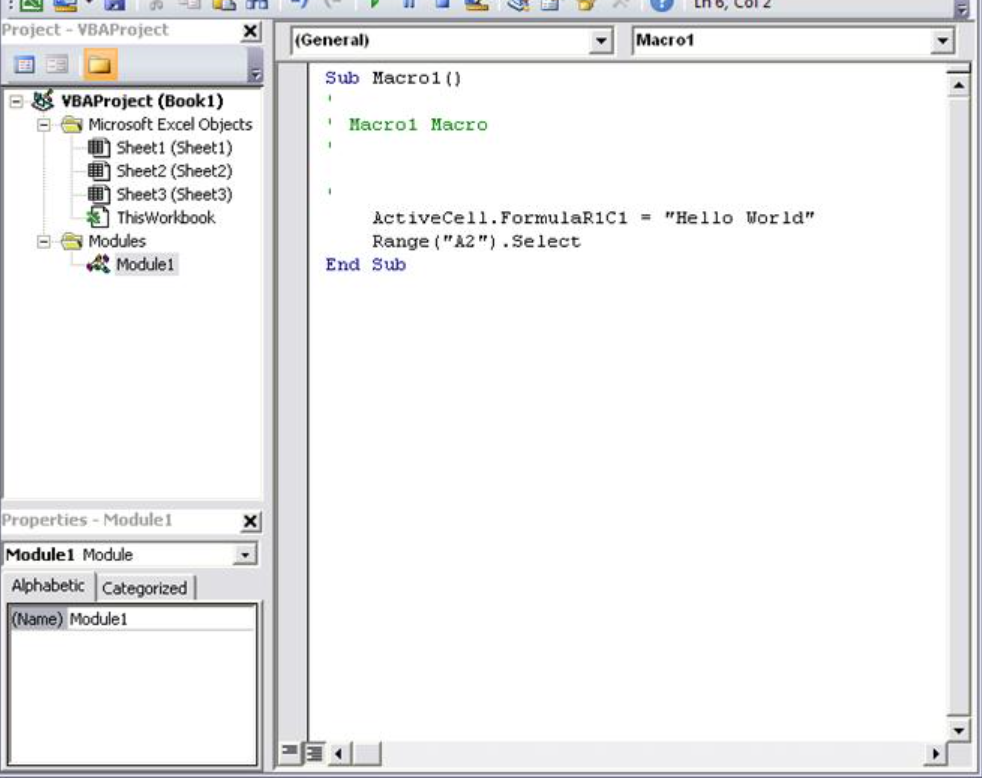
Source: learn.microsoft.com
VBA is a coding language built into Excel and other Microsoft Office apps. Though not technically a piece of software, this coding language is widely used by mechanical engineers to manage digital tasks and handle long workflows.
Engineers can also write simple code to automate calculations, run repetitive functions, and process data inside Excel. This reduces manual work and helps keep results clear and consistent.
VBA also lets engineers build small interfaces, connect to files, and control many parts of their models or studies through code.
Key Features
- Automated engineering calculations: Engineers use VBA to automate calculations for structural loads, part sizing, and other math-driven steps inside Excel.
- Custom functions and macros: Users can create functions that handle repetitive tasks and support consistent work across projects.
- Data handling for large studies: VBA can sort, clean, and process large amounts of data for parametric runs or batch tests.
- Simple user interfaces: Forms and controls help with data entry and make results easier to view without manual setup.
- Control of digital tasks across Excel: VBA connects to worksheets, files, and external libraries to run sequences that support modeling and report creation.
Bring Better Collaboration Into Every Mechanical Engineering Project
Mechanical engineers deal with tight timelines, complex parts, and constant updates. CADchat gives teams a clear way to discuss CAD models and stay aligned without extra tools or confusing file sharing. It keeps the focus on the work, not the process.
With this design review software, engineers can open a prototype with teammates, walk through each detail, and talk through changes in real time. This helps everyone understand the problem faster and move to the next step with confidence.
It also keeps the workflow clean and simple because all notes stay with the design. Nothing gets buried in long chats or email threads.
Engineers, suppliers, and non-technical stakeholders can jump in, review the same view, and help move the job forward. This saves time and removes friction that usually slows projects down.
FAQs About Mechanical Engineering Tools
What kind of tools does a mechanical engineer use?
Mechanical engineers work with simple hand tools, digital measuring tools, and design software. They use items like calipers, wrenches, and gauges during tests, and rely on programs like CAD to design parts and machines.
What equipment is used in mechanical engineering?
Mechanical engineering uses machines that help measure, build, and test parts. This includes CNC machines, 3D printers, and stress testing machines. Engineers also use thermal cameras, pumps, motors, and different lab tools to study how materials behave under real conditions.
What is the Big 4 in engineering?
The Big 4 usually refers to the four main engineering fields taught in most schools. These include mechanical, electrical, civil, and chemical engineering. They cover a wide mix of skills and open the door to many different career paths.